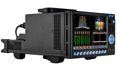
1. Who is SDI-STRESS designed for?
Our advanced SDI-STRESS option is available for stress testing and R&D evaluations of SDI interfaces and cables up to 12G. It’s predominantly used by R&D, manufacturing and Product Development Engineers.
2. Why is the SDI-STRESS option needed?
To help test products during the design and prototyping phases and to see how robust their new SDI I/O design is. It is also used to help validate and stress test new cable installations.
3. How do engineers use the SDI-STRESS toolset?
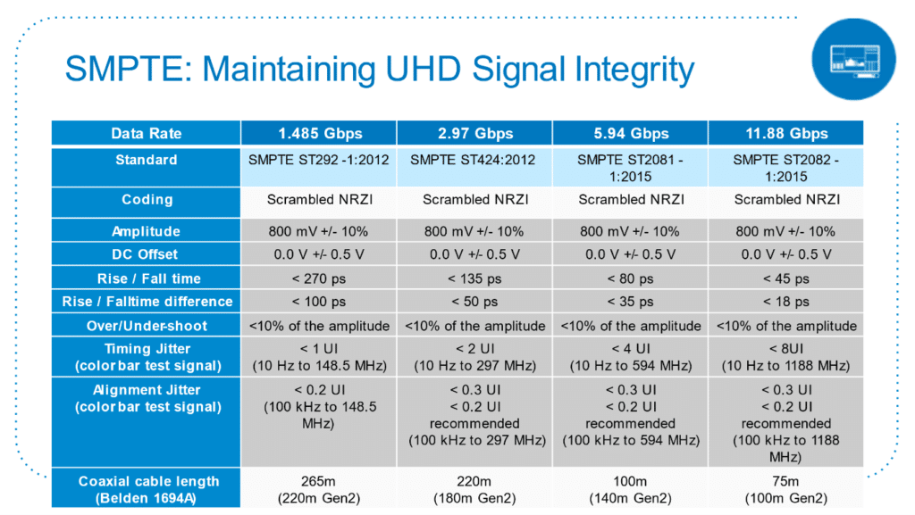
When designing SDI products, design engineers need to ensure that their design passes SMPTE’s SDI compliance specifications (see Figure 1 below). The SDI-STRESS tool makes the received signal harder to process by manipulating the signal via pathological test patterns, increasing the jitter, and adjusting the amplitude or slew rate. It then adds measurement tools to check the eye pattern or detect pathological conditions.
3.1. Optimise the transmitted SDI signal shape
SMPTE specify that over a 1-metre cable from the source, the analyser should receive an 800mV signal. The Eye diagram shows the shape of the transmitted signal at the receiver. In addition to the correct amplitude, the transmitted signal shape must have the correct rise and fall times (slew rate) with minimal overshoot or undershoot, with little noise and an open Eye.
The SDI-STRESS option adds an ‘Amplitude window’ into the Eye instrument. This allows a user to view Shorth Mean or standard amplitude histograms within specific regions of the Eye diagram. These can enable a designer to optimise the shape of different regions of the transmit signal. This is done by adjusting the PCB layout and value of output passives.
3.2. Test signal amplitude variation on SDI Receiver paths
The SMPTE specification also adds that a receiver should cope with 800mV with a +/- 10% margin.
The SDI-STRESS option allows the user to test a receiver with a signal amplitude beyond +/- 10% so developers can see how robust their design is. This can then be paired with long cable lengths to determine the maximum length of cable that the receiver equipment can cope with.
What happens if the receiving signal goes slightly outside of SMPTE’s spec? Does your product degrade nicely or does it fall off a cliff edge? If it falls off a cliff edge, how close to the cliff edge are you?
Therefore, you need to measure these conditions.
SDI-STRESS can adjust the transmitted amplitude to beyond +/-13% so developers can see how robust their design is.
3.3. Test signal slew rate on SDI Receiver paths
The SDI-STRESS option allows the user to set the slew rate to a 12G rise and fall time or an HD rise and fall time. This allows a user to test the effect of a signal with the wrong slew rate for that SMPTE standard.
3.4. Test signal jitter on SDI Receiver paths
Up to 128UI of Jitter (simulated sinusoidal variation in a signal’s timing from its nominal value) can be added to the test signal. This enables the receiver circuitry to be stressed beyond SMPTE limits to see when the product will begin to fail.
3.5. Test the SDI receiver’s ability to maintain a lock during pathological conditions
The Equaliser test pattern of 19 high bits and 1 low bit, or 19 low bits and 1 high bit, is difficult for an equalizer to correctly determine a high or low bit due to the DC component.
The PLL test pattern of 20 bits high, then 20 bits low has the minimum number of zero crossings for correct clock extraction.
These patterns occur statistically after scrambling at intervals of about once per frame.
The SDI-STRESS detects when pathological conditions have occurred and pulses a GPIO when detected. This enables a user to trigger an oscilloscope during a pathological condition and see the effect on the equaliser or recovered clock in detail.
4. Is that all of the SDI-STRESS tests?
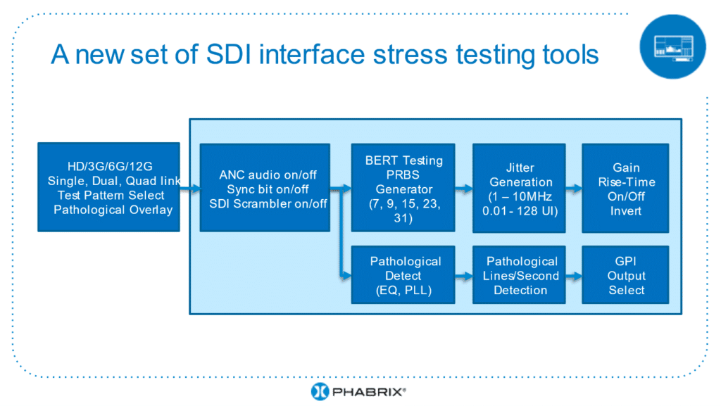
No, there are a number of other tests available (see Figure 2 below), including PRBS tests. PRBS stands for Pseudo-Random Bit Sequence and has been used in high-speed serial interfaces for many years. For SDI applications it is most common to use the PRBS23 sequence. PRBS31 is one of the recommended test patterns for 10 Gigabit Ethernet.
This test gives a bit error rate over a certain time duration so that you can see if an interface meets a specified bit error rate. It is a comparable concept to checking line CRCs over some time.
When run for a specified time, this method can be used to test installed cables. A transmitter at one end and a receiver at the other.
Other advanced generation tools that are provided in the Generator instrument, include, SDI BER Mode and Driver pre-emphasis.
The SDI BER mode function enables you to insert a number of SDI bit errors, these can be monitored by a receiver and analysed using the CRC and CS error checkers. This helps to determine how robust or tolerant the receiver input stage is to an error, or frequency of errors. The frequency of the bit error can be inserted at the appointed times affecting any word in the frame (or field) of the SDI flow.
You can also adjust driver pre-emphasis for SDI Out A, to pre-distort the signal edges of the eye pattern, to help optimize with signal integrity issues.
5. Can you describe more about the SDI Scrambler?
The SDI Scrambler is the part of the SDI interface that scrambles the signal before transmission. It ensures that there are many zero-crossing events no matter what the picture source is. The pathological test is the worst case, minimising zero crossing events. The receiver must descramble the data to return it to usable data again.
The option to disable the scrambler has been provided to enable video TRS comparison with a timing reference signal such as tri-level sync on an oscilloscope.
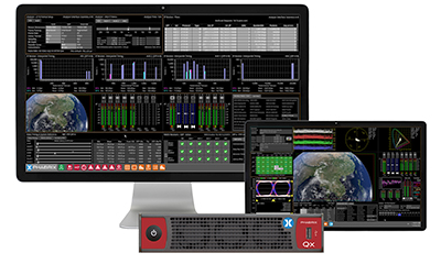
Click here to learn more about PHABRIX’s SDI Stress solution on the Qx Series
Related Products
QxP
The Portable QxL - 25G ST 2110 & 12G-SDI Generation, Analysis & Monitoring with Battery Power
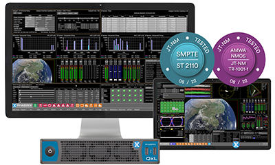
QxL
The world’s most compact, feature-rich rasterizer for realtime UHD IP workflows on a 25G network